1. Make sure you have version
2.0.0.71 or later.
2. Select menu Options - Misc., set the post Processor
to 'FourAxisLinear'.
3. Select menu Options - Foam, set the Wire Diameter
= 0.125 and the Step = 0.010.
4. Select menu Setup - Machine Setup - Machine, set
your machine to 4 axis w/ Linear.
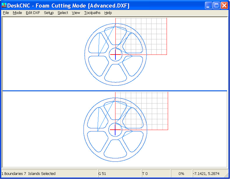
5. Select menu File - Foam Cutter - Open Top/Left/Larger
and select the advanced.dxf file.
a. The screen
should look like...
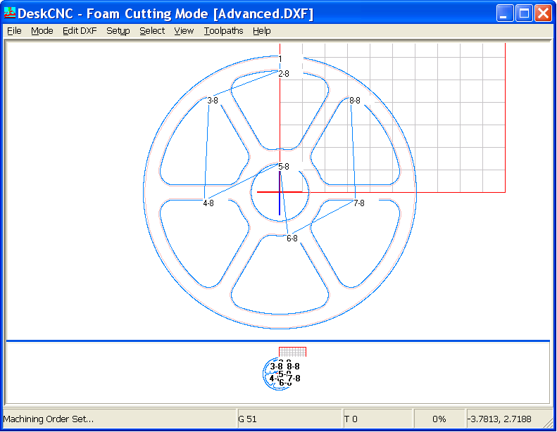
6. Select menu View- Information Tags, a marker is placed
at the beginning of each region.
7. Select menu Edit DXF - Set Machining Order.
a. Accept
the 'Start At' value of 1 and click OK.
b. Start with the
outer Circle and Left Click the outer circle (The Region Number will change
from 8 to 1).
c. Left Click the
spoke cutout at the top (it will change to Region 2).
d. Left Click the
spoke cutout to the bottom/left of the spoke cutout in 'c' above (region
3).
e. Left Click the
spoke cutout to the bottom of the spoke cutout in 'd' above (Region 4).
f. Left Click the
inner circle (Region 5).
g. Left Click the
spoke cutout to the bottom of the inner circle in 'f' above.
h. Left Click the
spoke cutout to the top/right of the spoke cutout in 'g' above.
i. Left Click the
spoke cutout to the top of the spoke cutout in 'h' above.
8. You should see the following...
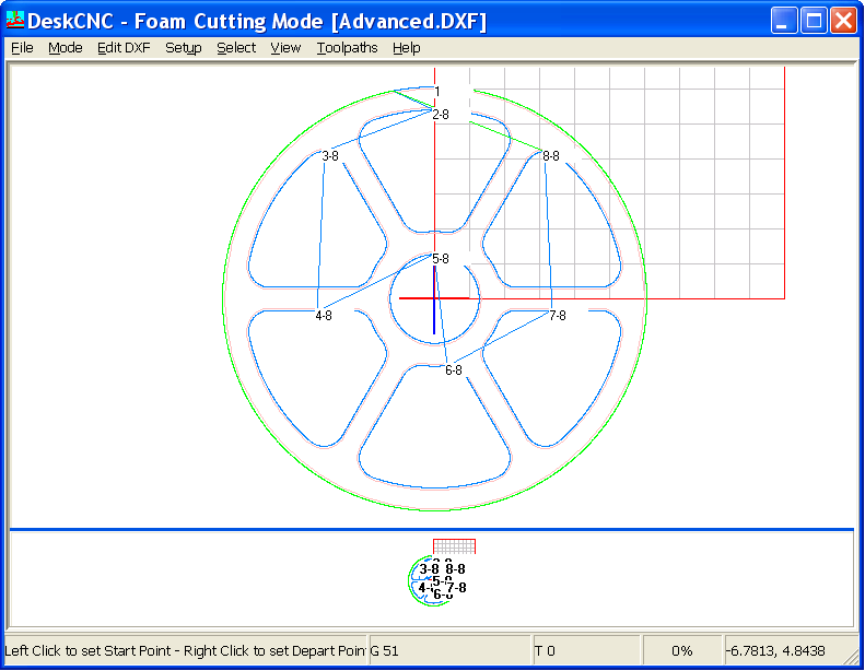
9. Select menu Edit DXF - Change Start/Depart.
10. Left Click on the Top Of the outer circle to set
the Start/Entry point.
11. Right Click the outer circle at about the 11:30 position.
This will set the Depart/Exit of the first region.
a. The outer circle
will be Blue (Selected Boundary Color) for the Start of the Cut and Green
(Selected Open Region Color) for the finish.
b. You should see....
12. Continue...
a. Left Click on
Region 2 directly below the end of the Blue portion of Region 1.
b. Right Click
on Region 2 at the 7:30 position.
c. Left Click Region
3 directly across from the end of the Blue portion or Region 2.
d. Right Click
Region 3 at the center of the Bottom.
e. Left Click Region
4 directly below the Blue portion of Region 3.
f. Right Click
Region 4 at the 3:00 position.
g. Left Click Region
5 directly across the Blue portion of Region 4.
h. Right Click
Region 5 at the Bottom Center.
i. Left Click Region
6 directly below the Blue portion of Region 5.
j. Right Click
Region 6 at the 3:00 position.
k. Left Click Region
7 directly across the Blue portion of Region 6.
l. Right Click
Region 7 at the Top Center.
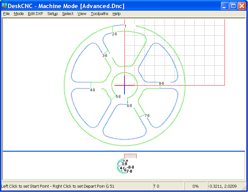
m. Double Click
Region 8 directly across the Blue portion of Region 7. This will set
the Start/Depart equal.
n. The Blue
line should make one continuous path to the Green line and back out to the
Start.
o. You should see....
12. Select menu Toolpaths - Four Axis Foam Cut and enter
the following...
a. Feedrate =
30.0, Approach Height = 0.5.
b. The Approach
Height is the absolute height the wire will traverse at to reach the Start
Point of each region.
c. Click the Create
button. Toolpaths are created with the approach settings.
11. Select menu Toolpaths - Run Machine.
a. Accept the
default filename and click OK.
b. The toolpath
GCode file is created and automatically loaded into the GCode Editor.
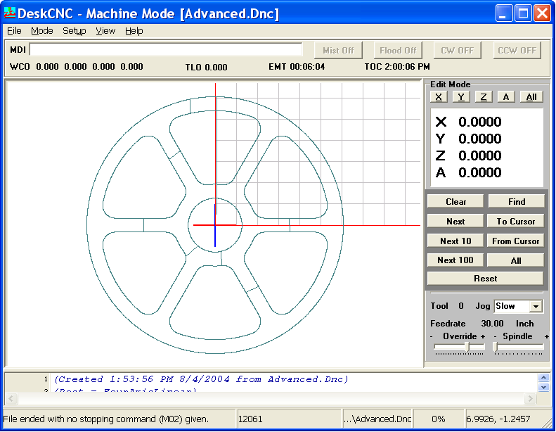
12. The GCode editor will look like this (in Edit mode)...
13. If you are not in Edit mode, select
menu Mode - Edit CNC.
14. Click the Reset button.
15. Continue pressing the Next 100 button and follow
the toolpaths as they make the wheel in one continuous motion.